
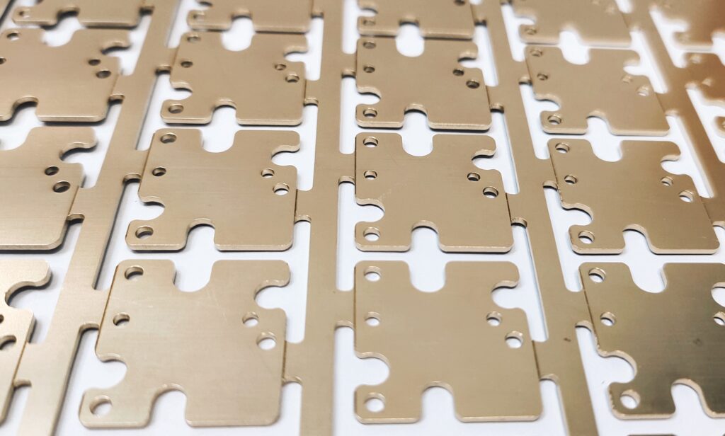
Why Do Automotive Engineers Rely on Metal Base PCB?
Heat can damage electronic components, typically through thermal cycling, solder joint fatigue, and gradual degradation. As a result, failures are often not detected until months after the vehicle leaves the factory. Under low-power conditions, FR4 material performs well. However, when the circuit board is subjected to higher loads—such as in LED driver circuits, motor controllers, or power inverters—FR4’s thermal conductivity of about 0.3 W/m·K becomes insufficient.
Heat accumulates faster than it can be dissipated, causing junction temperatures to exceed rated limits. After about 30,000 hours, these components begin to fail. This is where Metal Base PCB comes into play. They are not a high-end upgrade but a structural solution that addresses the limitations of FR4 under high power density conditions.
FR4 Has a Heat Problem That Most Designers Underestimate
Most PCB designers start their careers with FR4. This material is readily available, affordable, has well-defined properties, and is suitable for the vast majority of applications. The reason FR4’s glass-fiber-reinforced epoxy structure makes for a good electrical insulator is primarily that it does not conduct energy well. While this is beneficial for signals, it is not ideal for heat dissipation. When high-power components release heat onto an FR4 PCB, most of that energy cannot escape. The heat gradually accumulates and spreads, raising the temperature of adjacent components, causing solder joint degradation, and shortening the lifespan of all nearby components.
Furthermore, automotive operating environments typically range from 85°C to 125°C, compounded by vibration and humidity cycles. Engineers who have witnessed meticulously designed FR4 PCBs fail during in-vehicle thermal testing understand very well why they have begun switching to metal-core PCBs.
What a Metal Base PCB Actually Looks Like Inside
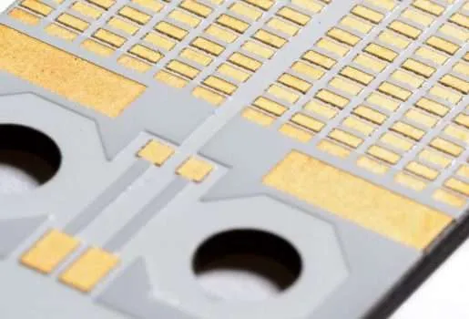
The structure is straightforward, but the details matter. A metal base PCB consists of three layers: a metal substrate at the base, a thermally conductive dielectric layer in the middle, and a copper circuit layer on top. The metal substrate does the thermal work. The dielectric layer provides electrical isolation while allowing heat to pass through. The copper layer carries the circuit.
Aluminum vs. Copper — Which Substrate and When
Aluminum is by far the more common choice. It offers thermal conductivity in the range of 1.0 to 3.0 W/m·K, depending on formulation — roughly 10 times better than FR4 — while remaining lightweight and cost-effective. For LED lighting assemblies, general power modules, and most automotive sensor applications, an aluminum substrate hits the right balance.
Copper substrate offers much higher thermal conductivity (typically 380 W/m·K) and is used in applications that truly require it, such as high-frequency power converters, RF modules, or designs with extreme heat flux density where aluminum can’t maintain junction temperatures within specs. The trade-off is cost and weight — copper substrate boards run considerably more expensive and heavier than their aluminum equivalents.
Thermal Conductivity, Dielectric Layer, and Why Both Matter
A common mistake in sourcing metal substrate PCB is focusing entirely on the substrate material while underspecifying the dielectric layer. The dielectric sits between the metal base and the copper circuit — and if its thermal conductivity is poor, it creates a thermal bottleneck that negates much of the substrate’s advantage.
Standard dielectric layers in metal base boards run from about 1.0 W/m·K up to 3.0 W/m·K for high-performance formulations. For most LED and power module applications, 1.5 to 2.0 W/m·K is adequate. For a metal base PCB for automotive electronics operating under sustained high-power conditions, specifying a dielectric at 2.0 W/m·K or above is worth the cost difference — it’s the difference between keeping junction temperatures 10–15°C lower under continuous load, which directly translates to component longevity.
Why is a Metal Base PCB Key for Automotive Electronics?
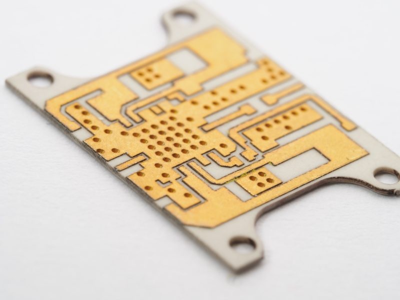
Consumer electronics can tolerate occasional temperature fluctuations, but automotive electronics cannot. The shift toward electric and hybrid vehicles has transformed thermal management from a secondary consideration after design into a primary design focus. Battery management systems, on-board chargers, DC-DC converters, and motor drive inverters all generate significant heat within compact enclosures.
In these applications, metal-substrate PCBs for the automotive electronics sector are the essential choice for ensuring that designs meet the thermal budgets required to achieve reliability goals.
AEC-Q100 certification, a wide operating temperature range, and vibration resistance are the basic requirements for automotive PCB procurement. Beyond these, dielectric formulations and substrate thickness become critical variables that distinguish truly high-performance circuit boards from those that barely meet specifications on paper but fail in real-world applications.
Where Metal Substrate PCB Gets Specified Beyond Automotive
Automotive is the most demanding context, but metal substrate PCBs are used wherever power density and heat dissipation intersect. LED lighting, both architectural and industrial, was an early mass-market application and remains one of the largest segments. Power supply modules, wireless amplifiers, and solar inverters all face the same issue: concentrated heat that FR4 can’t dissipate quickly enough.
The selection logic is consistent across all of them. When thermal resistance is limiting junction temperature and component life, and when adding a heatsink or improving airflow isn’t enough on its own, a metal base board addresses the problem at the substrate level rather than working around it.
Choosing the Right Metal Base PCB for Your Application?
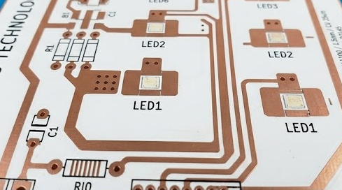
When selecting materials, focus on the substrate type, with the right dielectric resolving design bottlenecks. Surface finish impacts solderability and reliability, with common types—HASL, ENIG, and OSP—performing differently in high temperatures. Copper thickness affects current capacity and heat dissipation. For a metal base PCB in high-vibration environments, substrate stability is key. Thermal conductivity data from manufacturers is crucial, as small differences can impact validation tests at thermal limits.
