
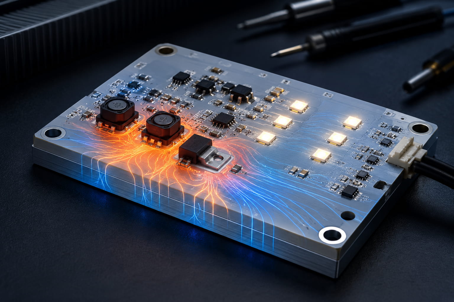
Why Aluminum Substrate PCB for Heat Dissipation Works Best
Run a high-power LED driver at full load for six hours on a standard FR4 board, and you’ll see the problem fast. The board runs hot, components drift out of spec, and lifespan drops sharply. Heat is the leading cause of premature electronic failure — and the substrate material you choose determines how well your design handles it.
That’s exactly where the aluminum substrate PCB for heat dissipation earns its place. Unlike conventional boards, it’s engineered from the ground up to move heat away from components quickly and reliably. For engineers and buyers dealing with thermal-critical applications, this isn’t a minor upgrade — it’s a fundamental design choice.
What Makes an Aluminum Substrate PCB for Heat Dissipation Different
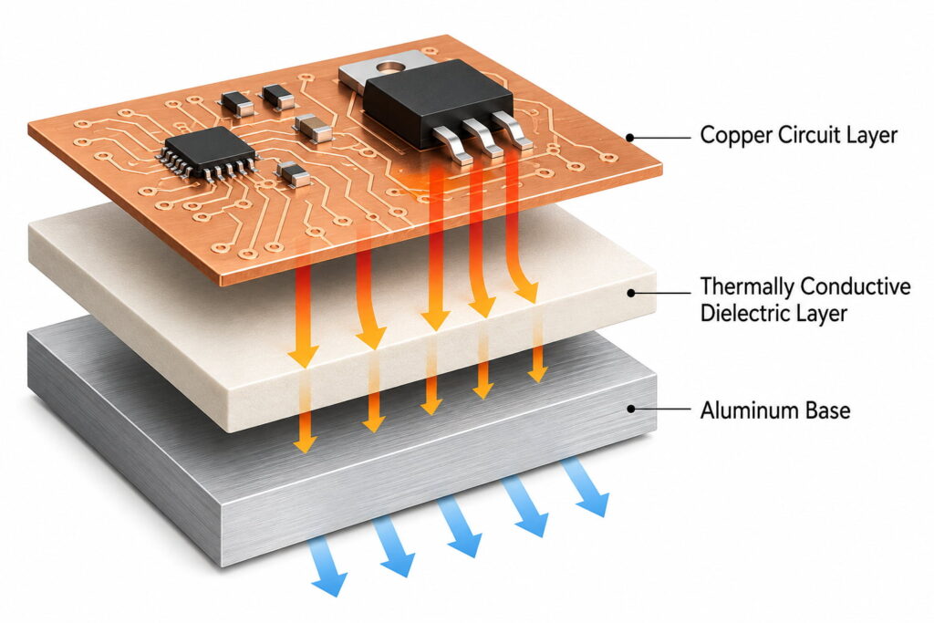
A standard FR4 board struggles with heat because the material itself is a poor thermal conductor — its thermal conductivity sits at just 0.3 W/m·K. An aluminum-substrate PCB for heat dissipation solves this with a three-layer structure that fundamentally changes how heat moves through the board.
The top layer is a copper circuit layer, typically 1-4 oz thick, where components are soldered. Beneath it sits a thermally conductive dielectric layer — this is the critical middle layer that electrically isolates the circuit while transferring heat downward. The base is an aluminum core, usually 1.0 mm to 3.2 mm thick, which spreads and dissipates heat across its surface far more effectively than any polymer-based substrate can.
The result? Thermal conductivity values for aluminum base PCB typically range from 1.0 W/m·K to 3.0 W/m·K, depending on the dielectric formulation. That’s up to ten times better than FR4. In practice, what this means is lower junction temperatures, more stable component performance, and significantly extended product life.
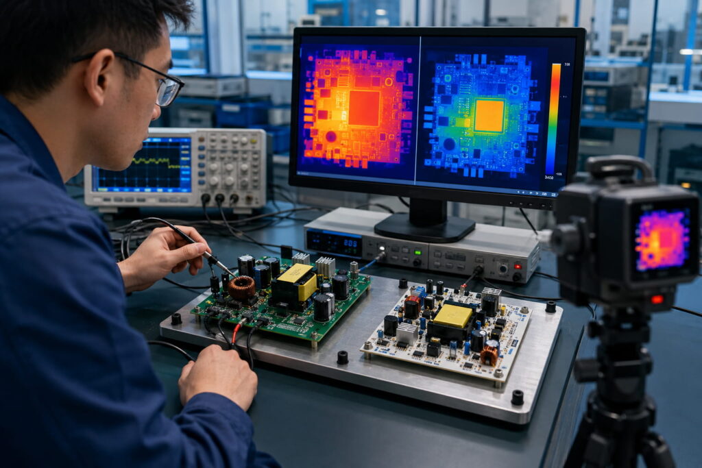
Aluminum Substrate PCB for Heat Dissipation Across High-Power Applications
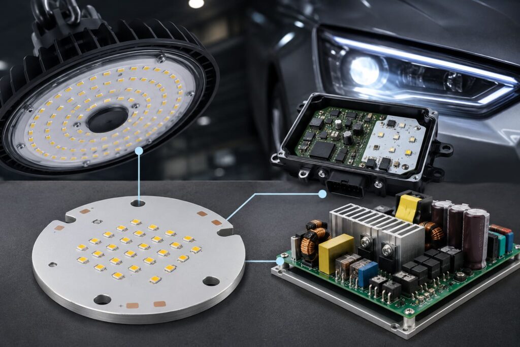
This design approach isn’t limited to one industry — aluminum core PCB thermal management shows up wherever power density is high and thermal failure is not an option.
LED Lighting is the most common use case. High-brightness LEDs generate concentrated heat at the die level. Without effective heat transfer, lumen output drops (a phenomenon called thermal droop), and lifespan shrinks from 50,000+ hours to well under 20,000 hours. LED aluminum substrate PCB keeps junction temperatures low enough to maintain both brightness and longevity.
Automotive Electronics increasingly rely on metal-core PCB solutions for engine control units, EV battery management systems, and LED headlight modules — environments where ambient temperatures are already high before the board even generates its own heat.
Power Supplies and Motor Drives are another natural fit. Switching regulators and MOSFET arrays generate significant heat during operation. Aluminum-backed circuit boards allow designers to increase power density without adding bulk heatsinks, thereby reducing enclosure size and overall system cost.
In each of these cases, the common thread is the same: components that run cooler, run longer.
How Aluminum Substrate PCB for Heat Dissipation Compares to Other Materials
Not every thermal challenge calls for the same solution. Here’s how an aluminum substrate PCB for heat dissipation stacks up against the most common alternatives:
| Material | Thermal Conductivity | Cost Level | Best For |
|---|---|---|---|
| Aluminum substrate PCB | 1.0–3.0 W/m·K | Medium | LED, power modules, automotive |
| FR4 | ~0.3 W/m·K | Low | Low-power general electronics |
| Copper base PCB | 380–400 W/m·K | High | Extreme thermal density, RF |
| Ceramic PCB | 20–170 W/m·K | Very High | High-frequency, high-temp environments |
A copper-base PCB wins in raw thermal performance, but its cost and weight make it impractical for most production runs. Ceramic PCB handles the highest temperatures but comes at a price point that rules it out for volume applications. FR4 remains the default for low-power designs, but it simply can’t cope with sustained heat loads.
For the majority of high-power commercial applications — especially LED and power conversion — an aluminum substrate PCB for heat dissipation hits the right balance of thermal performance, machinability, and cost.
Key Specs That Define Aluminum Substrate PCB for Heat Dissipation Performance
When evaluating an aluminum substrate PCB for heat dissipation, four specifications matter more than anything else.
The thermal conductivity of the Dielectric Layer is the single most important number. Standard dielectric layers deliver 1.0–1.5 W/m·K — adequate for most LED applications. High-performance dielectric formulations push this to 2.0–3.0 W/m·K, the range required for demanding power electronics. Don’t accept a spec sheet that only lists the aluminum core’s conductivity; the dielectric is the actual thermal bottleneck.
Dielectric Layer Thickness affects both thermal resistance and voltage isolation. Thinner dielectrics (75–100 µm) offer lower thermal resistance, meaning heat transfers faster. However, thinner layers also lower the breakdown voltage. For most 48V and below applications, 100 µm dielectric provides a strong balance; higher-voltage designs may require 150–200 µm to ensure safe isolation.
Copper Foil Weight determines both the current-carrying capacity and the heat the circuit layer itself generates. For standard LED drivers, 1 oz copper (35 µm) is common. High-current applications — motor drives, automotive modules — often specify 2 oz or 3 oz copper to reduce resistive heating in the trace itself.
Aluminum Base Thickness impacts both mechanical rigidity and heat spreading. A 1.6 mm base is standard for most panel formats. Applications with larger boards or higher mechanical stress often step up to 2.0 mm or 3.0 mm to prevent warping and improve thermal spreading across the board surface.
Together, these four specs define how effectively your aluminum core PCB thermal management system will actually perform under real operating conditions — not just in a datasheet comparison.
Choosing the Right Aluminum Substrate PCB for Heat Dissipation
The right choice comes down to matching these specs to your actual operating environment, not picking the highest number on every row. Over-specifying the dielectric adds cost without benefit if your application doesn’t generate the heat to justify it. Under-specifying it risks exactly the kind of thermal failure you’re trying to prevent.
Start with your maximum junction temperature target, work backwards to determine the thermal resistance budget, and select dielectric thickness and conductivity from there. If you’re designing for volume production, your PCB manufacturer should be part of this conversation early — not just a vendor you hand a completed Gerber file to. Get the substrate selection right at the start, and thermal management stops being a problem you solve after the fact — it becomes an advantage built into the design itself.
