
Strategies to reduce signal loss multilayer rigid-flex pcb
Ensuring optimal signal integrity throughout the board is essential when designing a PCB. In this article, we will explore the complexity of signal loss in multi-layer rigid-flex PCBs, help you understand the root causes, and develop practical solutions to help PCB designers overcome signal loss problems in multilayer rigid-flex PCB designs.
The root cause of signal loss in multilayer rigid-flex pcb
The dielectric materials used in circuit board construction significantly contribute to signal loss. The dielectric constant and loss tangent of these materials can affect signal integrity. Higher dielectric loss causes increased signal attenuation as it travels through the circuit board, especially at higher frequencies. Furthermore, the design and layout of the circuit board play a vital role. Proper impedance matching and controlled impedance routing are critical to minimizing signal distortion in multilayer rigid-flex boards. Insufficient trace width, spacing, or improper termination can cause impedance mismatches, resulting in reflections and signal attenuation. Signal loss can also occur during the manufacturing process itself. Factors such as copper surface roughness, inconsistent laminate thickness, and variations in plating quality can cause additional losses.
Optimize multilayer rigid-flex pcb trace routing to reduce signal loss
First, impedance control is critical to reducing signal attenuation. Precise control of trace width, spacing, and layer stacking is essential to maintaining consistent impedance throughout the PCB. Changes in impedance can cause signal reflections and losses, especially in high-frequency applications. Second, proper signal integrity analysis is required. Thorough simulation and analysis of signal behavior at different layers and under various conditions can help identify potential issues such as crosstalk, attenuation, and reflections. Minimizing signal attenuation is critical by selecting dielectric materials with low-loss tangents and suitable electrical properties.
Correct material selection achieves low signal loss
Among rigid profiles, conventional FR-4 (Flame Retardant-4) is widely used due to its cost-effectiveness and versatility. However, advanced materials such as high-frequency laminates or PTFE-based materials may be preferred for applications requiring higher frequencies and lower signal loss. These materials have lower dielectric constants and loss tangents, reducing signal attenuation at higher frequencies. Polyimide films are widely used in the flexible part due to their flexibility, thermal stability and excellent dielectric properties. Choosing a polyimide material with appropriate mechanical and thermal properties ensures the reliability of the loose part, especially in applications that require repeated bending or flexing.
Mitigating crosstalk
Mitigating crosstalk is essential to maintain signal integrity in multi-layer rigid-flex boards. Engineers must pay close attention to signal trace placement and ensure sufficient distance between signal traces to reduce electromagnetic coupling. Differential signaling for critical signals further helps reduce crosstalk because interference affects both traces equally, allowing the receiver to distinguish the signals. Maintaining consistent impedance on signal traces minimizes signal reflections and helps mitigate crosstalk. Shielding is a crucial technology for isolating sensitive signals from external interference. Ground planes and shields can be strategically placed to create a Faraday cage effect, reducing the impact of external electromagnetic interference and minimizing crosstalk.
Combined with grounding technology
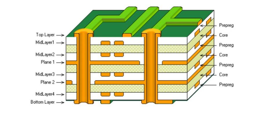
A fundamental aspect of bonding and grounding is establishing a solid ground plane. A continuous ground plane provides a low-impedance return path for signals, reducing ground loops and minimizing electromagnetic interference. Ensuring consistent ground planes across all layers of a multilayer rigid-flex PCB helps provide a stable reference point for signal currents. In high-frequency applications, employing a ground-signal-ground (GSG) routing strategy can be helpful. This involves having ground traces on both sides of the signal trace, effectively isolating the signal and reducing the risk of interference. The GSG method is precious for maintaining signal quality at higher frequencies.
Summarize
PCB designers can achieve superior signal integrity in electronic designs by addressing root causes, optimizing traces, selecting appropriate materials, mitigating crosstalk, and implementing grounding techniques. If you want to learn how we build your PCB, you can contact us at our official website.