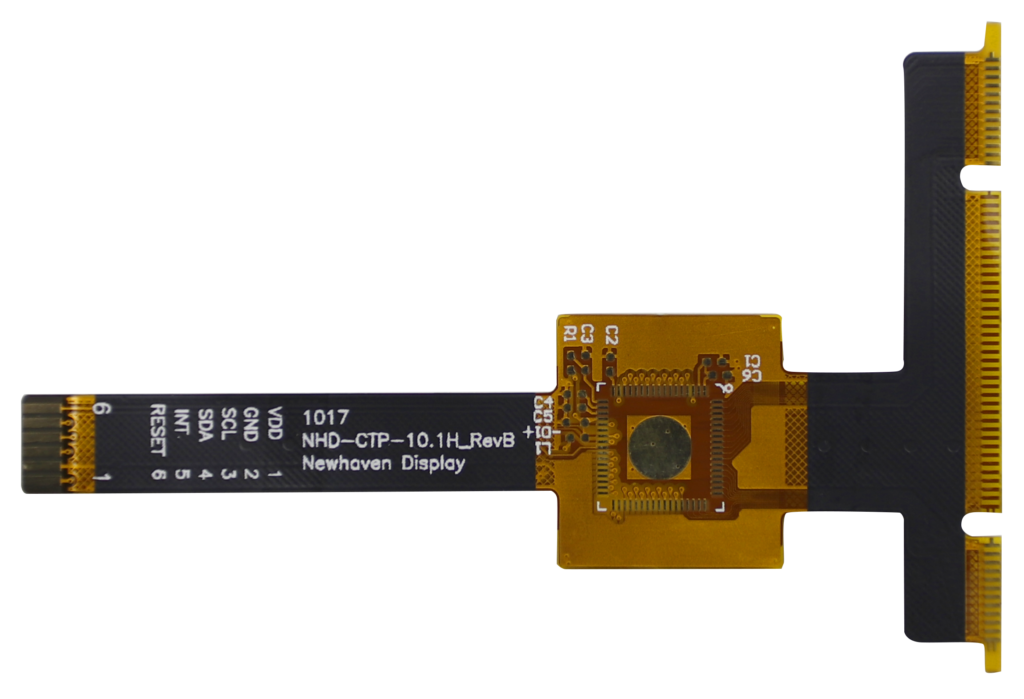
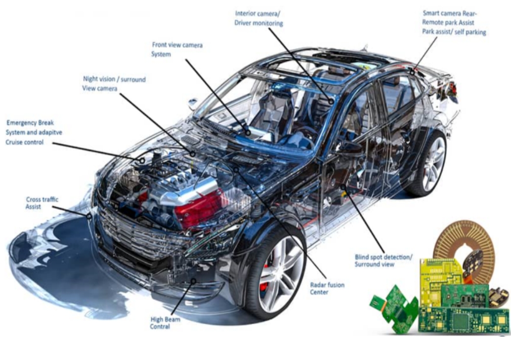
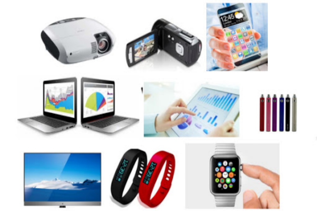
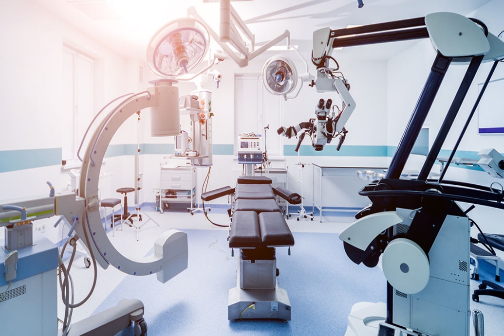
FPC PCB is a flexible circuit board usually constructed of flexible insulating substrate and conductive copper foil, especially when flexibility is required and space is limited. They are widely used in mobile devices, medical devices, automotive electronics and many other fields.
FPC PCB parameters:
1. Substrate type: FPC PCB usually uses flexible polyester film, polyimide (PI) or polyimide copper-clad foil as the substrate. These substrates offer high temperature resistance, chemical resistance and mechanical strength.
2. Conductive layer: Copper foil is usually used as the conductive layer. The thickness of the copper foil can be customized according to needs, usually between 1oz (ounces per square inch) and 3oz.
3. Thickness: FPC PCB is usually very thin, and its thickness is usually between 0.05 mm (50 microns) and 0.5 mm (500 microns).
4. Circuit line width and spacing: These parameters determine the conductive properties of the circuit. Line width and spacing selection depends on current loading, voltage requirements and the needs of the specific application.
5. Bending radius: The bending radius of FPC PCB refers to the minimum radius at which the circuit board can be safely bent or bent. This parameter is very important as it affects the durability of the board.
6. Pad and Connector Type: These parameters depend on how the FPC PCB is connected to other electronic components or devices. Pad and connector types can be customized to suit specific application needs.
7. Operating temperature range: The operating temperature range of FPC PCB depends on the material selection of the base material and conductive layer. Some FPC PCBs can operate in extreme temperature conditions.
Manufacturing process:
The manufacturing of FPC PCB usually includes the following steps:
Printing: The conductive lines of FPC PCB are usually manufactured on the substrate through printing technology or photolithography process.
Copper foil attachment: For double-sided FPC PCB, the copper foil is attached to the substrate through an adhesive or lamination process to form a double-sided conductive layer.
Etching: Using a chemical etching process to remove unwanted portions of copper foil to create a circuit pattern.
Electroplating: Increasing the thickness of copper foil through the electroplating process to improve the electrical conductivity of a circuit.
Cutting and Forming: FPC PCBs often need to be cut and formed to specific shapes and sizes.
Testing and Quality Control: Testing and quality control are performed at all stages of the manufacturing process to ensure that boards perform to specifications.