
What Is FPC PCB & Why It’s Taking Over from Rigid Boards
Modern electronic devices are becoming increasingly compact. Foldable smartphones, implantable medical sensors, and in-vehicle displays all face the same manufacturing challenge: how to integrate reliable circuits into spaces that bend, fold, and move? Flexible printed circuit boards (FPC PCB) are the answer. Flexible printed circuit boards (FPC PCB) have been around for decades. However, as devices become increasingly thin and lightweight, and product designers no longer accept the space constraints of rigid circuit boards, their adoption has accelerated significantly. Understanding what FPC PCBs are and what factors determine their durability will influence procurement decisions and directly impact the lifespan of the final product.
The Core Architecture Behind FPC PCB
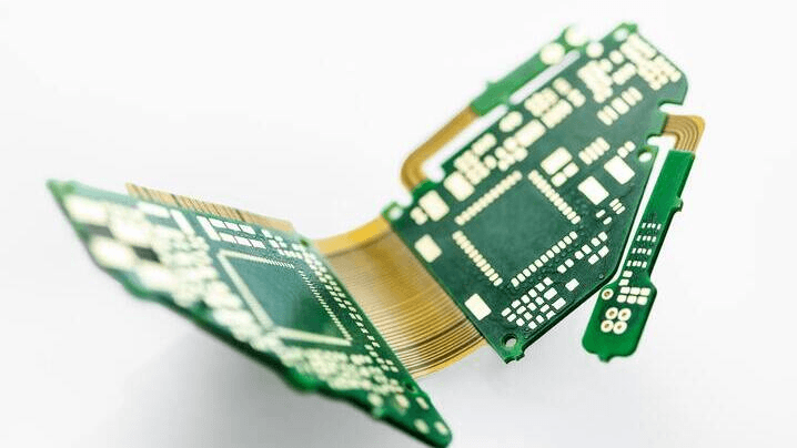
A flexible FPC PCB uses a flexible insulating substrate — typically polyimide (PI) film — valued for its thermal stability, chemical resistance, and ability to withstand repeated flexing without cracking. Copper foil forms the conductive layer, with a thickness ranging from 1 oz to 3 oz per square foot based on current needs. The overall board thickness is only 0.05 mm to 0.5 mm, making it far thinner than standard FR4 rigid boards.
Key performance parameters include: Operating temperature: Dependent on material grade. High-grade PI circuits can operate continuously above 150°C, ideal for harsh automotive under-hood environments where rigid PCBs fail. Bending radius: The minimum safe curve without delamination or conductor breakage. Mismatched specs are a leading cause of field failures. Trace width & spacing: Determine current capacity and signal density. Tighter spacing enables denser layouts but requires stricter manufacturing control.
How the Manufacturing Process Works
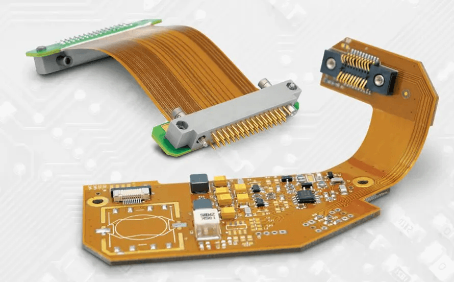
A flexible FPC PCB cable assembly is more than a bare flex circuit. It includes the flex board, connectors, terminations, stiffeners, and sometimes integrated components — delivered as a ready-to-install interconnect. The process starts with photolithography or screen printing to define conductive traces on the polyimide substrate. For double-sided designs, copper foil bonds to both faces through controlled-pressure adhesive or direct lamination. A chemical etching step then removes unwanted copper, leaving the precise circuit pattern behind.
Electroplating builds up conductor thickness and improves surface conductivity, particularly at via and pad locations. After that, laser cutting brings boards to exact dimensions — a method that achieves tolerances mechanical punching cannot match. Quality checks run at every stage: incoming material inspection, automated optical inspection (AOI) for trace defects, X-ray imaging for internal layer verification, and flying-probe electrical testing before shipment. A complete cable assembly goes through this sequence twice — once at the flex circuit level and again after full assembly.
FPC PCB vs. Rigid PCB: Which One Fits Your Design?
The real question is not which board is “better,” but which best fits your layout and performance needs. Rigid PCBs deliver higher layer density and work best for high-component-count assemblies with no flexibility demands. They also cost less in mass production for simple designs.
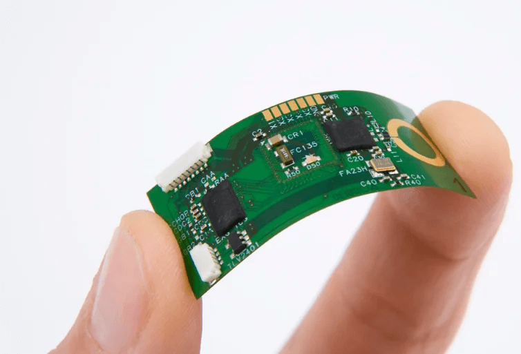
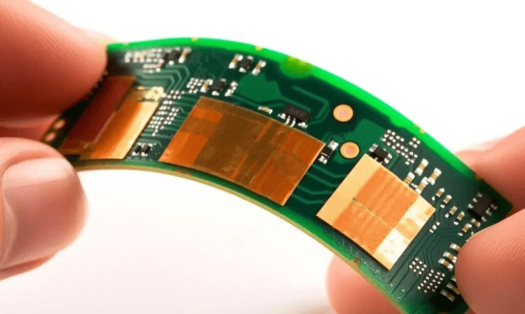
Flexible FPC PCBs outperform rigid boards in three key areas: Weight reduction: PI-based flex circuits are much lighter than rigid boards, making them popular in aerospace, medical wearables and portable devices. Space utilisation: They can bend, turn tightly, and wrap around components — essential for wearables and compact camera modules. Fewer interconnections: One FPC can replace multiple rigid boards, cables and connectors. Fewer solder joints reduce failure risks and improve long-term reliability.
Four Industries Where Flex Circuits Are Indispensable
The application range for flex circuits now extends well beyond consumer electronics. These four sectors currently drive the highest design activity:
Consumer electronics — smartphones, foldables, TWS earbuds, and smartwatches rely on flexible interconnects to hit their form factors. Screen-to-board connections in folding phones use flex circuits rated for hundreds of thousands of fold cycles.
Medical devices — implantable sensors, hearing aids, and minimally invasive surgical tools need circuits that conform to body geometry. Polyimide’s biocompatibility and thermal stability make it the dominant substrate choice in this sector.
Automotive electronics — dashboard displays, ADAS sensor modules, and in-seat electronics operate in environments with vibration, thermal cycling, and tight routing space. Flex circuits consistently outperform rigid boards in long-term durability here.
Industrial control — robotic joints, machine vision systems, and precision motion platforms use flex circuits at points of movement. Rigid boards simply crack under repeated articulation.
What to Demand From Your Supplier
Not all flex circuit production delivers equivalent results. The process window for polyimide-based circuits is tighter than for standard FR4, and manufacturing escapes typically don’t surface until the product is already in the field. Certifications are a baseline, not a differentiator. IATF 16949:2016 matters for automotive supply chains. ISO 9001:2015 is table stakes. UL recognition is required for most consumer and medical end uses. But certifications alone tell you nothing about day-to-day process control.
That’s where the automation level becomes the real indicator. High-volume FPC production at consistent yield requires AOI, flying-probe testing, and X-ray verification as standard steps — not optional services. Suppliers running 90%+ process automation deliver more consistent dimensional and electrical tolerances than those relying on manual inspection. Turnaround speed is equally important. Complex flexible FPC PCB cable assembly projects often cycle through multiple revisions before production release. A manufacturer with fast-turn capability and direct engineering support compresses that timeline — a genuine competitive advantage in fast-moving product development.
Getting the Specification Right From Day One
Flexible FPC PCBs are not drop-in substitutes for rigid boards. They’re purpose-built for specific geometries and reliability demands that rigid circuits can’t meet. The gap between a flex circuit that lasts the product’s full lifecycle and one that fails in the field almost always traces back to specification precision and manufacturing discipline.
Start with the bending radius — get that wrong and everything else is irrelevant. Match the substrate grade to the actual operating temperature. Request verified test data, not just a spec sheet. And if you’re sourcing a complete flexible FPC PCB cable assembly, confirm that the flex circuit and connector terminations were tested together as a system — because individual component approval doesn’t guarantee system-level performance.