Understanding Bend Radius in Rigid-Flex PCB Design
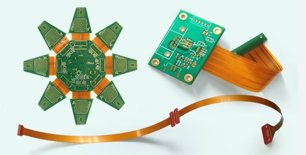
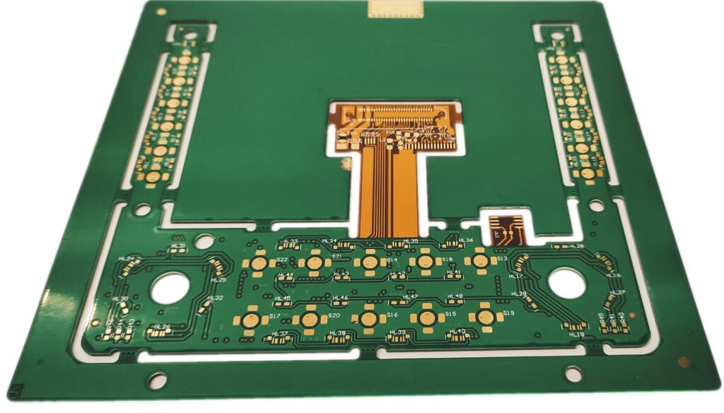
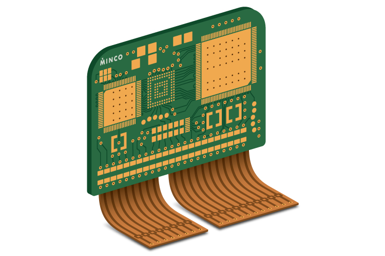
Rigid-flex PCB designs offer an innovative solution for industries requiring compact, adaptable, and reliable electronic systems. These designs combine rigid and flexible substrates, allowing engineers to create intricate and versatile circuit boards. One critical factor to consider in the design process is the bend radius of the flexible section. The bend radius dictates how tightly the flexible portion of the PCB can be bent without compromising its structural and electrical integrity. This article explores the concept of bend radius in Rigid-Flex PCB design and its impact on the board’s overall functionality and durability.
Factors Influencing Bend Radius in Rigid-Flex PCB Design
In Rigid-Flex PCB design, the bend radius is influenced by multiple factors, with material properties being one of the most significant. The flexible section of the PCB is typically made from polyimide, a material known for its durability and flexibility. However, not all flexible materials behave the same way. Some are more brittle, requiring a larger bend radius to avoid cracking under stress. The copper traces on the flexible part of the PCB also play a crucial role. Thicker copper traces are stiffer and require a larger bend radius to prevent damage.
The overall thickness of the PCB also impacts the required bend radius. A thicker PCB stack-up will be less flexible, so a larger bend radius is needed to ensure the design’s integrity. The number of layers in the flexible portion is another factor to consider. More layers generally result in a stiffer PCB, which requires a larger bend radius. Environmental conditions such as temperature fluctuations can further affect the material’s flexibility. Engineers must account for these variables to determine the appropriate bend radius for each design, ensuring that the PCB will perform reliably throughout its lifespan.

Material Selection and Bend Radius Considerations
When selecting materials for a Rigid-Flex PCB, it’s essential to consider how different materials impact the bend radius. Polyimide, a popular choice for flexible substrates, offers excellent flexibility and durability but comes with specific bend radius limitations. Polyimide-based materials typically require a larger bend radius than more rigid substrates. On the other hand, some high-performance materials may offer increased flexibility, allowing for tighter bends without compromising performance.
In addition to the flexible substrate, the type of copper used for the conductive traces can influence the bend radius. Thicker copper traces require a larger bend radius, while thinner traces allow more flexibility. Copper thickness also affects the rigidity of the PCB, and engineers must strike a balance between achieving a flexible design and ensuring reliable signal transmission. Engineers can design Rigid-Flex PCBs that meet functional and mechanical requirements by choosing the right combination of materials and understanding how they influence the bend radius.
Design Guidelines for Optimizing Bend Radius in Rigid-Flex PCBs
Engineers must follow some essential design guidelines to optimize the bend radius in a Rigid-Flex PCB design. First, the bend radius should generally be no less than 10 times the thickness of the flexible section. This guideline ensures that the PCB can bend without damaging the traces or the substrate. However, this is a basic rule of thumb, and specific materials or design requirements may necessitate adjustments.
Another critical design consideration is the placement of flexible sections. Engineers should avoid placing flexible parts in areas undergoing significant mechanical stress during use. By strategically positioning flexible sections in less constrained areas, designers can reduce the likelihood of excessive bending, ensuring the PCB’s longevity. In some cases, designers may also use rigid sections to provide support and minimize bending in critical areas of the PCB. Such strategic planning helps maintain the overall performance of the Rigid-Flex PCB while preventing unnecessary strain on the flexible components.

Impact of Temperature on Bend Radius in Rigid-Flex PCBs
Temperature fluctuations can significantly affect the bend radius of a Rigid-Flex PCB. Extreme temperatures—both high and low—can alter the material properties of the flexible substrate. In cold environments, materials like polyimide become more brittle, which increases the risk of cracking when the PCB is bent. Conversely, high temperatures can soften the material, making it easier to bend, but potentially compromising the overall mechanical integrity of the PCB.
Designers must consider the temperature range to which the PCB will be exposed during its intended use. Materials with higher temperature tolerance are often necessary for applications in harsh environments, such as aerospace, automotive, or medical devices. When designing Rigid-Flex PCBs for such applications, it’s crucial to test the PCB under real-world temperature conditions to ensure it maintains its functionality and reliability.
The Role of Simulation in Bend Radius Determination
Given the complexity of Rigid-Flex PCB design, simulation tools are invaluable in determining the optimal bend radius. These tools allow engineers to simulate various bending scenarios and identify potential failure points in the design. Using simulation software, engineers can visualize how the flexible portion of the PCB will behave under different stress conditions, helping them make informed decisions about the bend radius.
Simulations also allow for more precise calculations, reducing the risk of errors in the design process. Engineers can ensure that the PCB will perform reliably even under challenging conditions by simulating different materials, copper thicknesses, and bending angles. Additionally, simulations can help identify areas where the bend radius may need to be increased to prevent failure, saving time and resources during the prototyping phase.

Prototyping and Testing for Bend Radius Optimization
While simulations are helpful, prototyping and physical testing are crucial steps in optimizing the bend radius of a Rigid-Flex PCB. Once the design is finalized, a prototype should be created to test how the PCB behaves in real-world conditions. This testing phase allows engineers to assess the PCB’s mechanical and electrical performance and make necessary adjustments.
Prototyping provides valuable feedback on the design’s bendability and durability. Engineers can test how the PCB performs when subjected to bending stresses, ensuring that it meets the required specifications for both flexibility and functionality. Any issues discovered during testing can be addressed before the final product is manufactured, reducing the risk of failure in the field. Prototyping and testing are essential for ensuring that the Rigid-Flex PCB will perform reliably in its intended application.
Achieving Optimal Bend Radius in Rigid-Flex PCB Design
Understanding the bend radius in Rigid-Flex PCB design is critical to creating reliable, high-performance boards. Engineers can optimize the bend radius to ensure the durability and functionality of the PCB by considering factors such as material selection, copper thickness, temperature fluctuations, and simulation tools. An adequately designed bend radius helps prevent damage, reduce mechanical stress, and ensure that the PCB performs as expected, even in harsh environments.

