
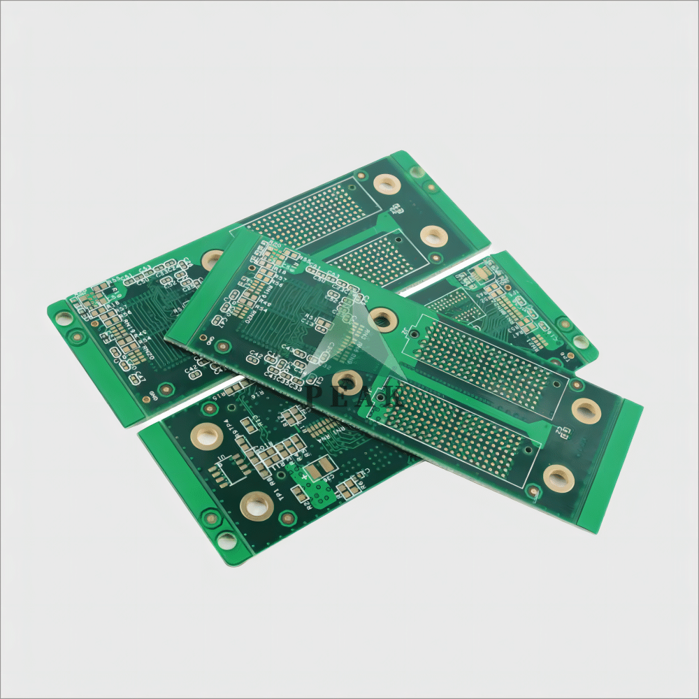
SSD PCB: Understanding the Core of Solid-State Drives
The SSD PCB is the heart of any solid-state drive, connecting all essential components that handle data storage and transmission. It houses the NAND flash memory, controller, power management ICs, DRAM (if present), and passive components that regulate the operation. Unlike mechanical drives, SSDs rely entirely on electronic components, which makes the PCB layout and design critical to performance, durability, and thermal management. A well-constructed SSD PCB boosts speed and reliability, ensures better heat dissipation, and extends the device’s lifespan.
Anatomy of an SSD Circuit Board
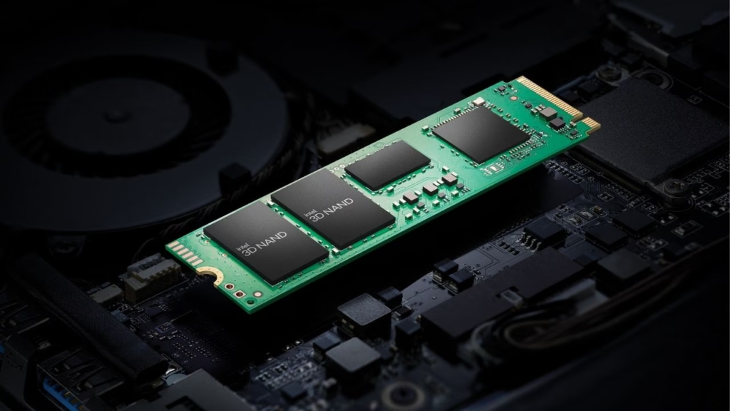
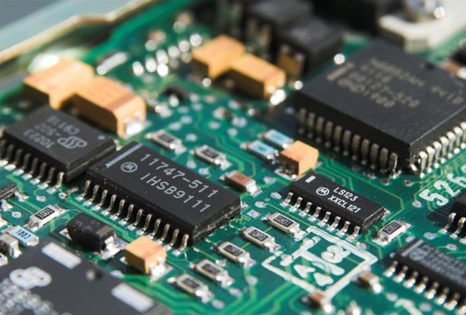
An SSD circuit board typically includes a controller chip that functions as the brain of the drive, managing data flow between the host system and NAND flash memory. The NAND chips store actual data, while DRAM provides temporary storage to enhance performance. There are also voltage regulators and capacitors to ensure stable power delivery. The layout and quality of the PCB determine the effectiveness of communication between these components, which in turn affects overall read/write speeds and latency. For high-capacity SSDs, multilayer PCBs are often used to accommodate more chips and reduce electromagnetic interference.
Form Factors and Interfaces That Define Modern SSDs
SSD PCBs come in various shapes and sizes, depending on the interface type: SATA, M.2, or U.2. SATA SSD PCBs are usually rectangular and housed in a 2.5-inch enclosure. M.2 PCBs are much smaller and connect directly to the motherboard, supporting either SATA or NVMe protocol via PCIe lanes. U.2 SSDs cater to enterprise-level systems with a different layout optimized for server use. The choice of form factor and interface affects not just the physical dimensions of the PCB but also the number and type of components it can support, influencing performance and compatibility.
Inside the Manufacturing Process of High-Performance SSDs
The production of an SSD PCB involves precision engineering and the fabrication of multilayer circuit boards. Manufacturers use advanced materials like FR-4, polyimide, or ceramic substrates to ensure thermal stability and signal integrity. Surface-mount technology (SMT) is used to place micro-components accurately. The PCB is subjected to strict quality control processes, including X-ray inspection, automated optical inspection (AOI), and signal testing. High-end SSDs may also feature conformal coatings or electromagnetic interference (EMI) shielding for added durability in harsh environments. The better the PCB design and build quality, the more resilient the SSD will be under stress.
SSD PCB Failures and Troubleshooting
SSD failures often stem from controller malfunction, power surges, or damaged PCB traces. Common symptoms include the SSD not being recognized by the BIOS or sporadic read/write errors. While consumer-level users are usually advised to replace the drive, data recovery professionals often repair or replace the SSD PCB using donor boards. This process requires a precise match between the firmware and NAND configuration. Hence, understanding the PCB layout and chip markings becomes crucial. Investing in SSDs with reinforced PCBs and power loss protection features is a wise choice for users with mission-critical data.
The Role of PCB Design in SSD Performance
PCB design plays a significant role in dictating the thermal profile, power distribution, and signal transmission within an SSD. Poor design can result in thermal throttling, signal noise, or permanent failure. High-performance SSDs often feature copper planes, thermal vias, and heat sink integration to maintain optimal temperatures under load. Additionally, the routing of PCIe lanes, placement of decoupling capacitors, and separation of the ground and power planes all impact signal integrity and operating efficiency. Engineers continually optimize these factors to extract every bit of speed from modern solid-state drives (SSDs).

SSD PCB Customization and Niche Applications
With the rise of embedded systems and edge computing, customized SSD PCBs have found applications in the industrial, automotive, and aerospace fields. These PCBs are often rugged, supporting extended temperature ranges and featuring specialized firmware. Small-form-factor SSD PCBs, like M.2 2230, are increasingly popular in ultra-compact devices. Custom boards may include hardware encryption modules, security key storage, or enhanced power filters. Manufacturers in niche sectors often require PCBs that meet strict standards, such as MIL-STD-810 or ISO 16750.
Future Trends in SSD PCB Development
As SSD technology continues to evolve, so does the complexity of the SSD PCB. Expect to see more integration of AI-assisted memory management, integrated voltage regulation modules, and chipsets that enable modular upgrades. With PCIe Gen 5 and Gen 6 on the horizon, PCB signal integrity and material choices will become even more crucial. Thermal management innovations, such as vapor chambers or phase change materials, could be embedded directly into the PCB stack. Ultimately, the SSD PCB is more than just a circuit board—it’s the foundation on which the speed and reliability of modern digital life are built.